
Next Generation Electric Aircraft Systems Powered By HIL and Real-Time Simulation
Electric aircraft systems are transforming aviation by enabling cleaner, more efficient operations. Central to this progress are Hardware-in-the-Loop (HIL) and real-time simulation technologies that help validate propulsion and energy management systems under real-world conditions—early in development and at full scale.
These systems use electric propulsion technology, which is more efficient and environmentally friendly compared to traditional fossil fuel-powered aircraft. As the demand for cleaner and quieter transportation options grows, electric aircraft and air taxis are poised to change the way we travel.
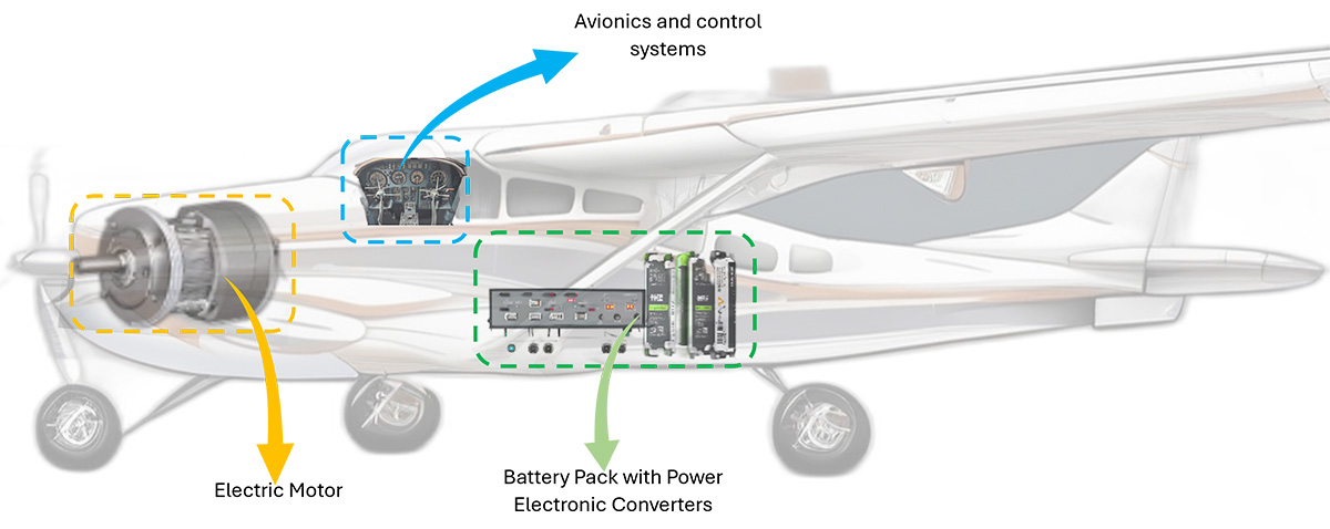
Fig 1. Electric Aircraft
Electric aircrafts use electric motors powered by batteries or other energy storage systems. This eliminates the need for traditional internal combustion engines and reduces the carbon emissions released into the atmosphere. Electric propulsion is also quieter than traditional engines, which can help reduce noise pollution around airports and urban areas.
Air taxis can become a new form of urban air mobility that can provide on-demand, direct air travel for short distances within cities or between nearby regions. These systems typically use electric vertical takeoff and landing (eVTOL) technology, allowing them to operate from small landing pads rather than traditional runways. This flexibility opens up new possibilities for transportation by providing faster and more convenient travel options for passengers.
One of the challenges that electric aircraft taxi systems is that the limited energy density of present battery technology—this limits the range and endurance of electric aircraft, making them better suited for shorter flights rather comparted to long-distance travel. However, ongoing research and development in battery technology are helping to address these issues, and future advances may enable electric aircraft to fly longer distances.
Another important aspect of electric aircraft taxi systems is their potential to improve safety. Electric propulsion systems have fewer moving parts than traditional engines, which can reduce maintenance requirements and the risk of mechanical failure.
Regulatory bodies around the world are working to establish standards and regulations for electric aircraft and air taxi systems. These efforts are essential for ensuring the safety and reliability of these new transportation options. As the industry continues to grow, these regulations will play a crucial role in shaping the future of electric aviation.
Public reception and infrastructure development are other key factors that will influence the success of the air taxi systems. Educating the public about the benefits of electric aviation and addressing any concerns they may have will be important for gaining support. Likewise, developing infrastructure such as charging stations will be crucial for the greater adoption of air taxis.
Why Electric Aircraft Real-Time Emulation?
At Impedyme, our real-time HIL and PHIL testing solutions are designed to accelerate electric aircraft development by offering scalable, modular platforms that integrate seamlessly with MATLAB/Simulink. These systems enable engineers to emulate flight dynamics and power demands with high accuracy and safety. As the industry shifts towards electric propulsion, these testing methods help ensure the safety, reliability, and efficiency of new technologies before they are integrated into actual aircraft. One key reason for conducting real-time emulation is the ability to simulate complex and dynamic operating conditions. Electric aircraft systems, including propulsion, energy storage, and control components, must work together seamlessly in various scenarios. By emulating different flight conditions and power demands in real time and full power flow, we thoroughly test how the system performs and identify potential issues that may arise during actual flights.
Real-time emulation tests allow for the integration of real hardware components with a simulated environment, providing a more accurate and representative test platform. This approach enables us to assess the behavior of actual components, such as electric motors and batteries, under simulated flight conditions. This testing is essential for verifying the performance and safety of the hardware in a controlled setting.
Another advantage of real-time emulation is the ability to validate control algorithms. Electric aircraft rely heavily on control systems to manage energy distribution, propulsion, and other critical functions. By testing these control systems in real time, we can ensure they operate properly and efficiently in response to changing conditions during flight. Real-time emulation also facilitates rapid iteration and optimization of system designs. It allows us to quickly modify components or control algorithms based on test results, thereby allowing for faster development cycles and improved performance. This iterative process is essential for electric aircraft technology and staying competitive in the industry.
Last, but definitely not least, real-time emulation typically uses Simulation models to perform the testing process, which is pretty easy and intuitive to build.
Simulink Model of an Electric Aircraft
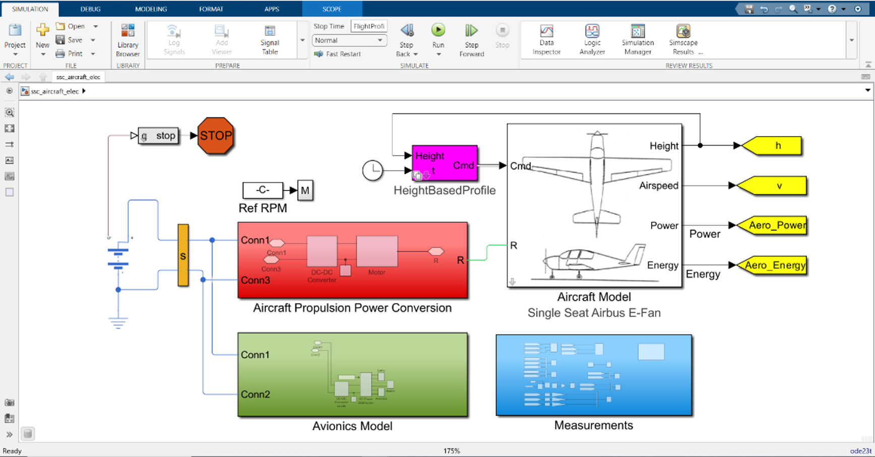
Fig 2. Electric Aircraft System’s Simulink Model
The Simulink model is not only used for conceptual design—it is also deployable directly to Impedyme’s CHP platform for real-time execution and testing. This model includes propulsion, dynamics, and avionics subsystems—each ready for hardware-level validation.
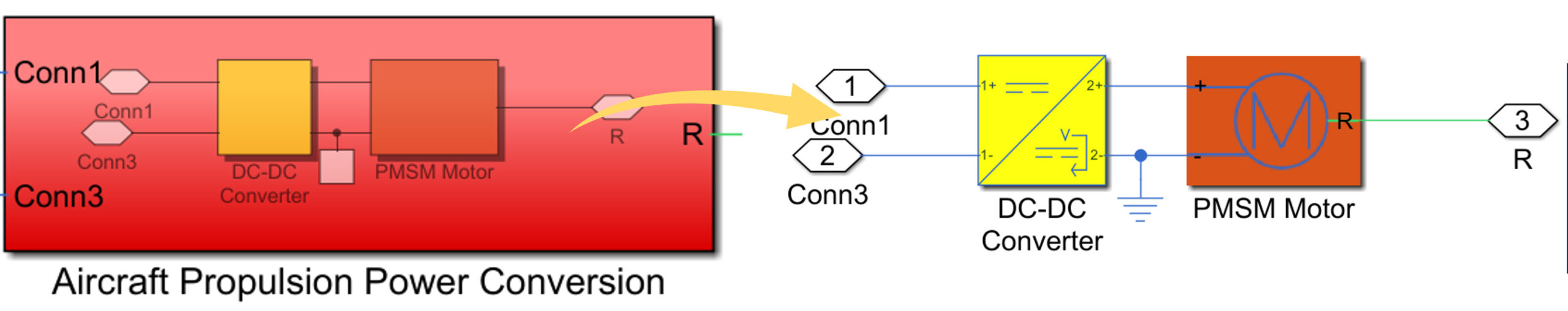
Fig 3. Electric Aircraft Propulsion Model
The aircraft propulsion model consists of a DC-DC converter linked to a permanent magnet synchronous motor (PMSM). The PMSM delivers torque to the electric flight propellers, enabling the aircraft to maneuver and maintain speed. The motor operates in a torque-control mode, with speed controllers using proportional (Kp) and integral (Ki) gain values to achieve control of the motor's operation.
The aircraft dynamic model provides a simulation of the aircraft's flight characteristics against various design criteria, such as flight range and duration. The model can be customized by adjusting various parameters to test different design aspects. Within this model, there are other sub-blocks such as the thrust command block and the longitudinal dynamics block.
The thrust command block allows you to specify the desired thrust levels for the aircraft's propellers, which directly influences the aircraft's speed and acceleration. By adjusting the thrust command, you can simulate different flight scenarios and observe how the aircraft responds to changes in thrust levels.
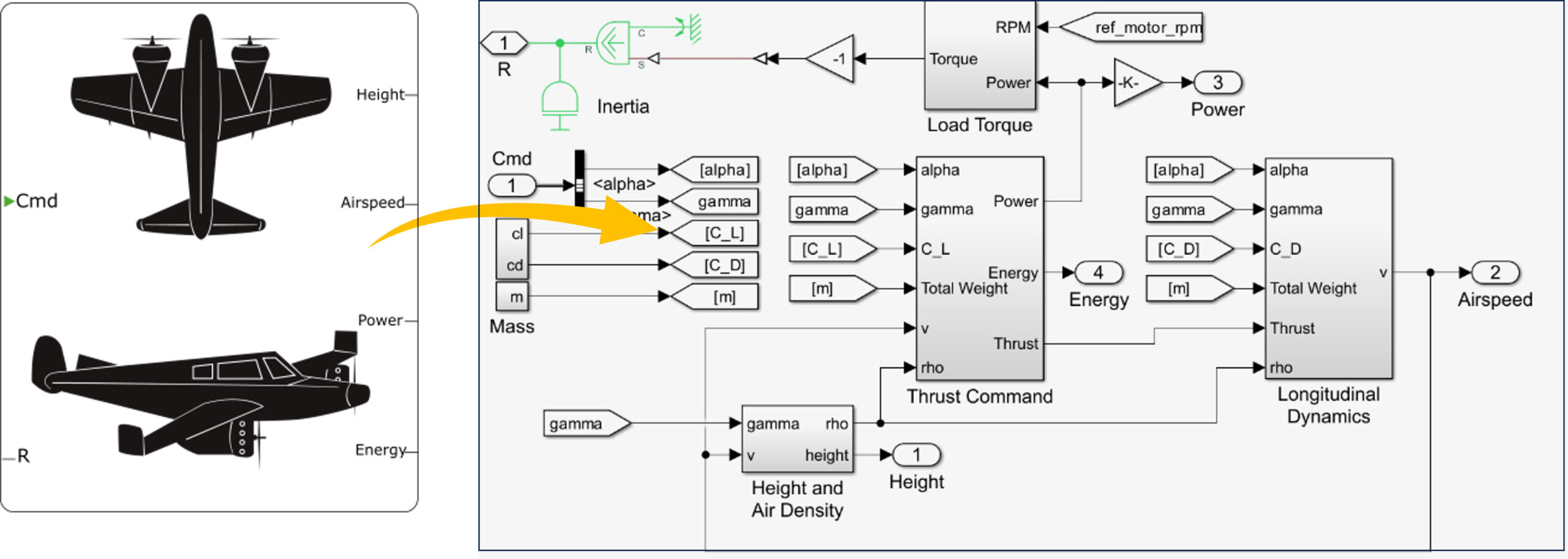
Fig 4. Electric Aircraft Dynamics’ Model
The longitudinal dynamics block simulates the aircraft's movement along the forward axis, including pitch (upward and downward movement) and lift characteristics. This block is important for us to analyze how the aircraft will behave under various flight conditions, such as takeoff, landing, and cruising.
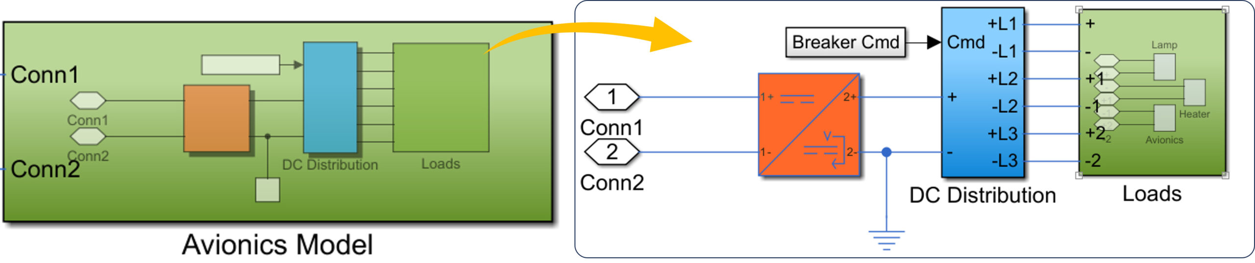
Fig 5. Electric Aircraft Avionics Model
Lastly, the avionics model manages the power distribution and small DC loads within the electric aircraft. The model includes a power converter that steps down the voltage from the battery to supply power to various loads such as lamps and heaters through a DC distribution system. This ensures that all electrical systems on board the aircraft operate efficiently and reliably.
Now that the electric aircraft systems’ models are built using Simulink, let’s get introduced to Impedyme’s CHP technology to emulate and test the developed models in real-time.
Impedyme’s CHP Technology
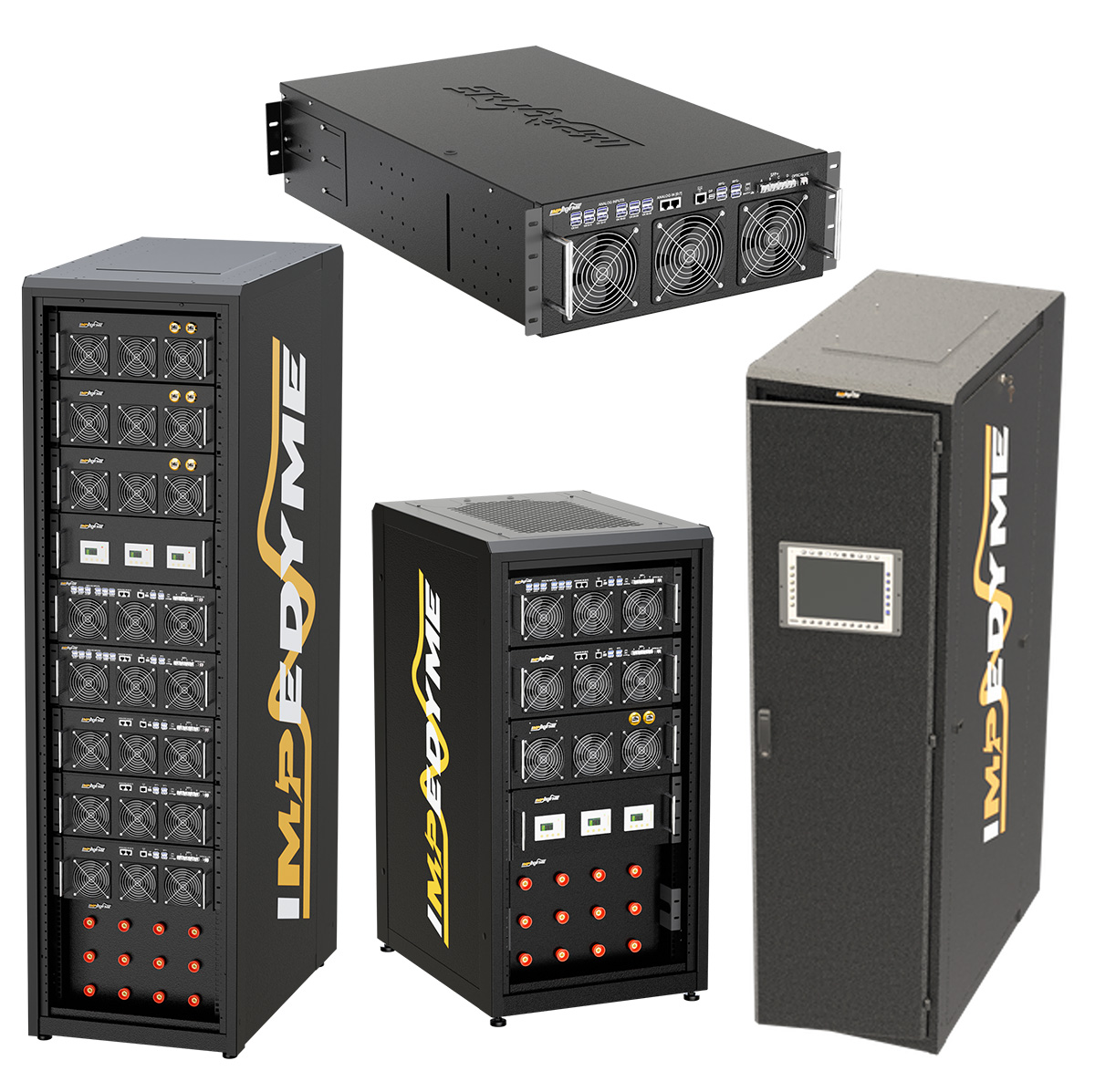
Fig 6. Impedyme’s CHP Cabinet
Impedyme’s CHP platform is uniquely suited for electric aircraft validation. From high-frequency propulsion drives to battery system integration, CHP empowers aviation engineers to test complex systems in real time, under full-load flight conditions. From battery management systems to electric aircrafts, CHP empowers manufacturers to optimize performance, enhance reliability, and accelerate time-to-market for their designs. Its modular design ensures flexibility to adapt to evolving testing needs, while its intuitive Simulink interface streamlines the testing.
Some of Impedyme CHP’s features include:
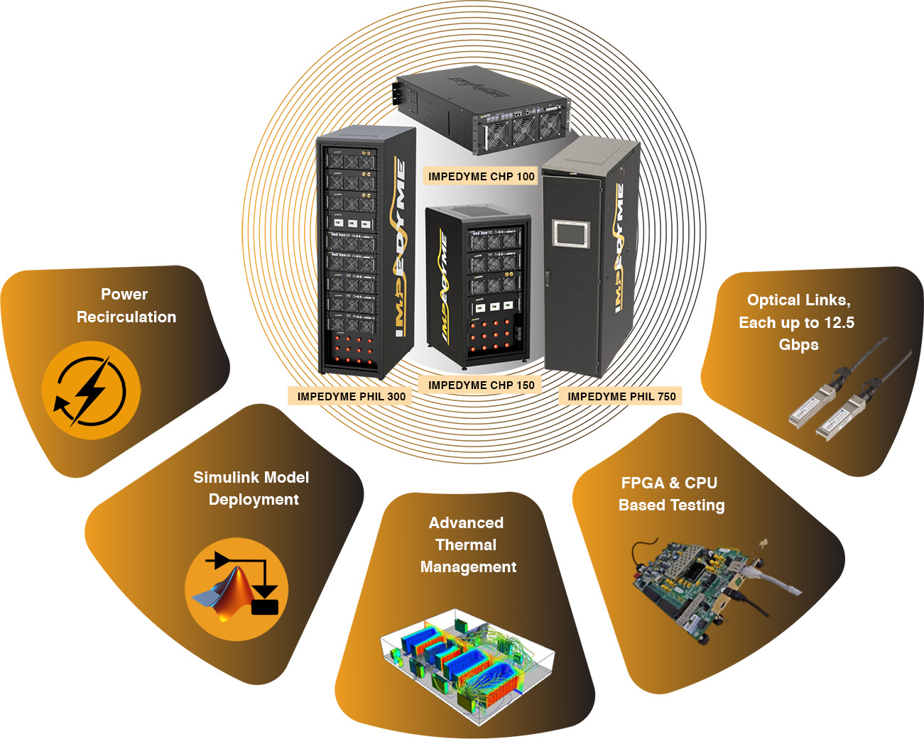
The Impedyme’s emulation solutions mimic your MATLAB Simulink models that can be used for high power tests, up to a few Mega Watts scale, for bandwidths up to 20 kHz. Simply connect the optical links to our cabinets and deploy your models to begin the testing. The cabinets have multiple optical links each up to 12.5 giga-bits per second. For simulations with ultra-low step-times, the equipment supports FPGA-based tests, that allows you to have time steps as low as a few nanoseconds. Moreover, the FPGA brings in a better performance for your real-time emulation since the processing speed of an FPGA is much higher than that of a CPU.
Also, for high-speed emulations, the individual FPGAs of the drawers can communicate among them. The testing using Impedyme’s CHP is straightforward as it uses Simulink designs. Our products come with a wide range of pre-designed models, which you can customize the designs according to your needs and requirements. Furthermore, if we were to emulate both the input and the output side of the power systems, we can have a circulating power flow. Since the power is recirculated, we only must feed in power losses from the grid. By having such a technology can reduce the power requirements of your lab for testing large power systems. Moreover, during the real-time emulation of your models, our integrated thermal management utilizes an advanced liquid + air cooling technology that ensures that does not require any additional chiller for cooling. Thus, we use Impedyme’s CHP to emulate the developed marine power systems models in real-time.
Now that we have developed the aircraft model, let us see how the connections are given to kickstart the testing process.
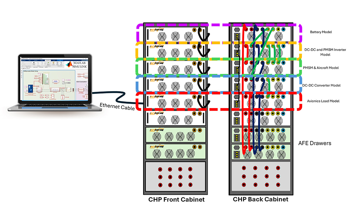
Fig 7. Electric Aircraft Power Systems Emulation: Impedyme’s CHP Connection Diagram
We allocate the first drawer, that is the top-most drawer, for the battery model and the second drawer for the PMSM’s dc-dc and inverter model. Likewise, the third drawer is dedicated for the aircraft’s PMSM motor model. Finally, the dc-dc converter and the avionics load models are deployed into the subsequent two drawers, respectively. The last two, that is the two bottom-most drawers are dedicated for the Active Front end Converters that provide the DC coupling for the emulation.
Now, let’s see how the connections are made to allocate these drawers. the power connections are given on the backside of the cabinets. The DC supply from the active front end drawer is given to the battery model drawer and the battery voltage is provided to the dc-dc/inverter model’s input supply. The second drawer emulates the action of an dc-dc and inverter and converts the DC from the battery to 3-phase AC, which are subsequently provided to the motor drawer below, and finally the DC power from the battery is stepped down by the dc-dc converter drawer and provided to the avionics load model below. The DC coupling is given back to the active front end drawer from the avionics load model to have a circulating power flow. Since the connections are complete, we are now ready to test.
This modular allocation not only mirrors the aircraft’s physical system architecture but also enables isolated fault injection and subsystem-level tuning. By closing the power loop through active front-end drawers, energy efficiency and thermal behavior can also be emulated with precision.
Emulation Results
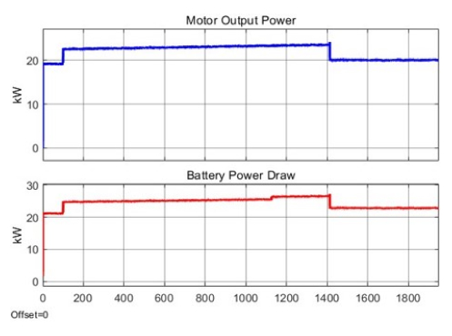
Fig 8. Motor and Battery Response of the Emulation
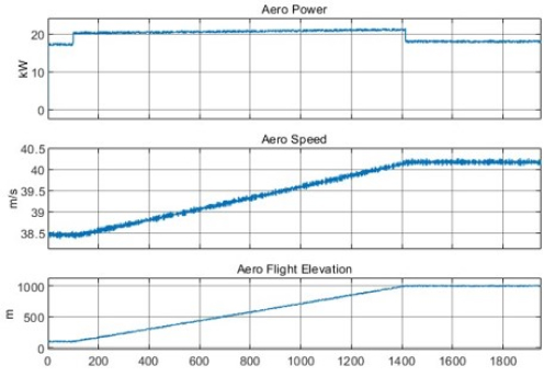
Fig 10. Aircraft Dynamics
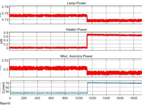
Fig 9. Emulation Response of Avionics Loads
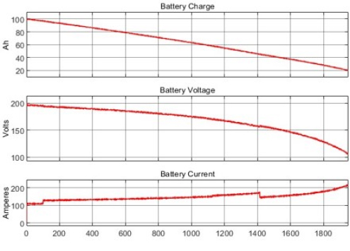
Fig 11. Battery Dynamics
References
- Zhao Wang, Steve Miller (2018). Electric Aircraft Model in Simscape (https://www.mathworks.com/matlabcentral/fileexchange/64991), MATLAB Central File Exchange. Retrieved November 14, 2018.
- 225-238, March 2022, doi: 10.1109/TTE.2021.3119231.